
Free Download ASTM A53 Standard : 18 Check Items

ASTM A53 Standard is the most common standard for carbon steel pipes, no matter for welded steel pipes or seamless carbon pipes and tubes, bare pipes and zinc coated pipes. It’s widely applied in many industries, like water, common piling or construction applications. If one is in steel pipe industry and don’t know ASTM A53 standard, you will be ashamed !
ASTM A53 Standard
Free Check and Download
1. Scope of ASTM A53 Standard
ASTM A53 is standard specification for pipe, steel, black and hot dipped, zinc-coated, welded and seamless. This specification2 covers seamless and welded black and hot-dipped galvanized steel pipe in NPS 1⁄8 to NPS 26 [DN 6 to DN 650] (Note 1), inclusive, with nominal wall thickness (Note 2) as given in Table X2.2 and Table X2.3. It shall be permissible to furnish pipe having other dimensions provided that such pipe complies with all other requirements of this specification.Supplementary requirements of an optional nature are provided and shall apply only when specified by the purchaser.
2. Application of ASTM A53 Standard Pipes
Steel Pipes ordered under this specification is intended for mechanical and pressure applications and is also acceptable for ordinary uses in steam, water, gas, and air lines. It is suitable for welding, and suitable for forming operations involving coiling, bending, and flanging.
3. Types and Grades
This specification covers the following types and grades:
- 3.1 Type F—Furnace-butt-welded, continuous welded Grade A.
- 3.2 Type E—Electric-resistance-welded, Grades A and B,
- 3.3 Type S—Seamless, Grades A and B.
Note:
- Type F is not intended for flanging.
- If Type S or Type E is required for close coiling or cold bending, Grade A is the preferred grade; however, this is not intended to prohibit the cold bending of Grade B pipe.
- Type E is furnished either nonexpanded or cold expanded at the option of the manufacturer.
4. Materials and Manufacture of ASTM A53 Pipes
- 4.1 The steel for both seamless and welded pipe shall bemade by one or more of the following processes: open-hearth, electric-furnace, or basic-oxygen.
- 4.2 If steels of different grades are sequentially strand cast, identification of the resultant transition material is required. The steel producer shall remove the transition material by any established procedure that positively separates the grades.
- 4.3 The weld seam of electric-resistance welded pipe in Grade B shall be heat treated after welding to a minimum of 1000 °F [540 °C] so that no untempered martensite remains, or otherwise processed in such a manner that no untempered martensite remains.
- 4.4 When pipe is cold expanded, the amount of expansion shall not exceed 11⁄2 % of the specified outside diameter of the pipe.
5. Chemical Properties of ASTM A53 Standard Steel Pipes
You can see the following chemical composition of Grade A and Grade B of A53 carbon pipes.

6. Mechanical Properties: Tensile strength and Yield strength
For ASTM A53 standard tensile tests other than transverse weld tension tests, the yield strength corresponding to a permanent offset of 0.2 % of the gage length or to an extension of 0.5 % of the gage length under load, the tensile strength, and the elongation in 2 in. or 50 mm shall be determined, and the tension test results shall conform to the applicable tensile property requirements given in the following chart:

7. Hydrostatic Test
- The hydrostatic test shall be applied, without leakage through the weld seam or the pipe body.
- Plain-end pipe shall be hydrostatically tested to the applicable pressure given in Table X2.2, and threaded-andcoupled pipe shall be hydrostatically tested to the applicable pressure given in Table X2.3. It shall be permissible, at the discretion of the manufacturer, to perform the hydrostatic test on pipe with plain ends, with threads only, or with threads and couplings; and it shall also be permissible to test pipe in either single lengths or multiple lengths.
8. Ultrasonic Test
Ultrasonic and Electromagnetic Inspection—Any equipment utilizing the ultrasonic or electromagnetic principles and capable of continuous and uninterrupted inspection of the weld seam shall be used.
9. Flattening Test
According to ASTM A53 Standard, a test specimen at least 4 in. [100 mm] in length shall be flattened cold between parallel plates in three steps, with the weld located either 0° or 90° from the line of direction of force as required by 7.3.3.2 or 7.3.3.3, whichever is applicable.
- During the first step, which is a test for ductility of the weld, except as allowed by 7.3.5, 7.3.6, and 7.3.7, no cracks or breaks on the inside or outside surface at the weld shall be present before the distance between the plates is less than two thirds of the specified outside diameter of the pipe.
- As a second step, the flattening shall be continued as a test for ductility away from the weld. During the second step, except as allowed by 7.3.6 and 7.3.7, no cracks or breaks on the inside or outside surface away from the weld shall be present before the distance between the plates is less than one third of the specified outside diameter of the pipe but is not less than five times the specified wall thickness of the pipe.
- During the third step, which is a test for soundness, the flattening shall be continued until the test specimen breaks or the opposite walls of the test specimen meet.
10. Weight (Mass) Tolerance
The weight (mass) of the pipe shall not vary more than +/- 10 % from its specified weight (mass), as derived by multiplying its measured length by its specified weight (mass) per unit length, as given in Table X2.2 or Table X2.3, or as calculated using the relevant equation in ASME B36.10M.
For exmaple:
For 12 inch, STD, HFW pipes, the unit weight as per ASME B36.10 is 73.86 kg/m, then the actual weight of pipes must within +/-10% x 73.86 kg/m.
11. Outside Diameter Tolerance
For pipe NPS 11⁄2 [DN 40] or smaller, the outside diameter at any point shall not vary more than 6 1⁄64 in. [0.4 mm] from the specified outside diameter. For pipe NPS 2 [DN 50] or larger, the outside diameter shall not vary more than +/-1 % from the specified outside diameter.
For exmaple:
For 12 inch, STD, HFW pipes, the outside diameter shall be within +/-1% x 323.9mm. If exceed this range, then pipes is not qualified according to ASTM A53 Standard.
12. Thickness Tolerance
The minimum wall thickness at any point shall be not more than 12.5 % under the specified wall thickness.
For exmaple:
For 12 inch , STD, HFW pipes, as per ASME B36.10, the thickness is 9.53mm, then the acceptable thickness range is +/-12.5% x 9.53mm.
13. End Finish
- Pipe with a specified wall thickness greater than 0.500 in. [12.7 mm], and all double extra-strong weight pipe, shall be plain-end square cut.
- Pipe of standard-weight or extra-strong weight, or in wall thickness less than 0.500 in. [12.7 mm], other than double extra-strong weight pipe, shall be plain-end beveled with ends beveled to an angle of 30°, +5°, -0°, measured from a line drawn perpendicular to the axis of the pipe, and with a root face of 1⁄16 in. 6 1⁄32 in. [1.6 mm +/- 0.8 mm].
14. Workmanship and Surface Finish
The pipe manufacturer shall explore a sufficient number of visual surface imperfections to provide reasonable assurance that they have been properly evaluated with respect to depth.
- Surface imperfections that penetrate more than 12.5 % of the specified wall thickness or encroach on the minimum wall thickness shall be considered defects.
- The finished pipe shall be reasonably straight.
- The pipe shall contain no dents greater than 10 % of the pipe diameter or 1⁄4 in. [6 mm], whichever is smaller,measured as the gap between the lowest point of the dent and a prolongation of the original contour of the pipe.
- Wall thickness measurements shall be made with a mechanical caliper or with a properly calibrated nondestructive testing device of appropriate accuracy. In the case of a dispute, the measurement determined by use of the mechanical caliper shall govern.
- For the removal of imperfections and defects by grinding, a smooth curved surface shall be maintained, and the wall thickness shall not be decreased below that permitted by this specification. It shall be permissible to reduce the outside diameter at the point of grinding by the amount so removed.
15. Test Method
The test specimens and the tests required by this specification shall conform to those described in the latest issue of Test Methods and Definitions ASTM A 370.
16. Pipe Length
- Unless otherwise specified, pipe lengths shall be in accordance with the following regular practices: Except as allowed by 16.1.2 and 16.1.4, pipe lighter than extra-strong weight shall be in single-random lengths of 16 to 22 ft [4.88 to 6.71 m], with not more than 5 % of the total number of threaded lengths furnished being jointers (two pieces coupled together).
- For plain-end pipe lighter than extra-strong weight, it shall be permissible for not more than 5 % of the total number of pipe to be in lengths of 12 to 16 ft [3.66 to 4.88 m].
- Uniform length as customer requirements.
17. Mill’s Test Certificate
- The manufacturer or supplier shall, upon request, furnish to the purchaser a certificate of compliance stating that the material has been manufactured, sampled, tested, and inspected in accordance with ASTM A53 Standard (including year-date), and has been found to meet the requirements.
- For Types E and S, the manufacturer or supplier shall furnish to the purchaser a chemical analysis report.
18. Pipes Marking
Each length of pipe shall be legibly marked in the following sequence to show:
- Manufacturer’s name or mark,
- Specification number (year-date not required), Pipe that complies with multiple compatible specifications may be marked with the appropriate designation for each specification.
- Size (NPS and weight class, schedule number, or specified wall thickness; or specified outside diameter and specified wall thickness),
- Grade (A or B),
- Type of pipe (F, E, or S),
- Test pressure, seamless pipe only (if applicable, in accordance with Table 4),
- Nondestructive electric test, seamless pipe only (if applicable, in accordance with Table 4),
- Unless another marking format is specified in the purchase order, length shall be marked in feet and tenths of a foot, or metres to two decimal places, dependent upon the units to which the pipe was ordered. The location of such marking shall be at the option of the manufacturer.
- Heat number, lot number, run number, or a combination thereof shall be marked at the option of the manufacturer, unless specific marking is specified in the purchase order. The location of such marking shall be at the option of the manufacturer.
- Any additional information desired by the manufacturer or specified in the purchase order.
For example:
HYSP ASTM A53 GRADE B TYPE E 323.9MM X 9.53MM X 11.98MM HEAT NO. 1998
New Products

ASTM A335 Grade P22 Alloy Pipe Steel 3inch SCH120
HYSP supplies high quality ASTM A335 Grade P22 Alloy Pipe Steel and tube 3inch SCH120 for high pressure and temperature applications.
ERW Steel Tubing 12inch ASTM A53 B
HYSP Steel Pipe supply you ERW Steel Tubing 12inch ASTM A53 B SCH40 or API 5L ERW steel pipes for your gas and oil line pipe or water pipes application.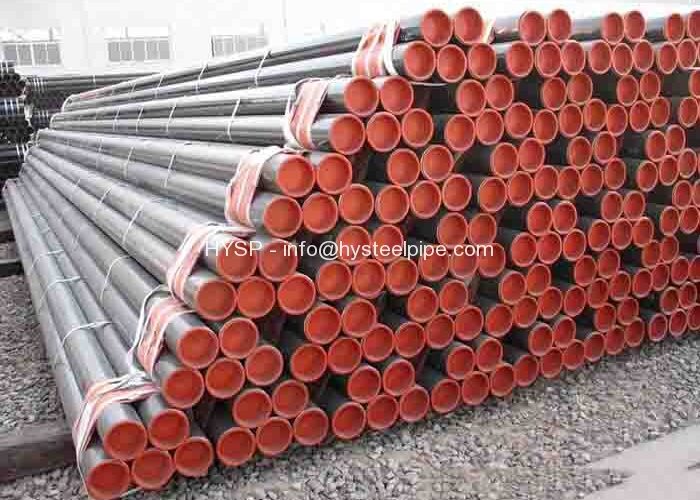
API 5L B ERW Steel Tube OD 426MM
HYSP makes API 5L B ERW Steel Tube OD 426mm x 9.53mm WT DRL for your applications like gas and oil line pipe. we can customize size and steel grade per request.
L235 ERW Pipe EN10224 OD 323.9mm
HYSP steel pipe makes L235 ERW Pipe EN10224 OD323.9mm steel tubes for the conveyance of water and other aqueous liquids. we also produce as required size.